


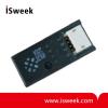
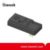
BasicLine BL 510 Standard-Signal Isolators - BL 510


The warning symbol on the device (exclamation point in triangle) means: Observe instructions
- Model Number: BL 510
- Data Sheet:

- Quantity:
- - +
Product Specification
1. General Information
The warning symbol on the device (exclamation point in triangle) means: Observe instructions!
Warning!
Protection against electric shock
For applications with high working voltages, take measures to prevent accidental contact and make sure that there is sufficient distance or insulation between adjacent
devices.
Take protective measures against electrostatic discharge (ESD) when switching the ranges.
Caution
Only trained and qualified personnel should install the BasicLine BL 510 standard-signal isolators. Do not connect the devices to power supply before they are professionally installed. Do not change the measuring range during operation. Be sure to observe the national codes and regulations for installation and selection of cables and lines.
You must install a two-pole circuit breaker between device and mains supply (next to the device). It must be easily accessible and clearly identifiable by the operator. Mains supply must be protected by a fuse ≤ 20 A.
2. Intended Use
The BasicLine BL 510 standard-signal isolators are used for galvanic isolation of 0(4) to 20 mA and 0 to 10 V standard signals. DIP switches allow selection of calibrated input and output signals (see rating plate).
Do not operate the device outside the conditions specified by the manufacturer, as this might result in hazards to operators or malfunction of the equipment.
The system installer is responsible for the safety of the system in which the device is integrated.
3. Configuration
Set the DIP switch according to the table on the housing (factory setting 0 ... 20 mA to 0 ...
20 mA).
4. Mounting, Electrical Connection
The units are snapped onto TS 35 standard rails and laterally fixed by suitable end brackets. See dimension drawing for terminal assignments. Conductor cross-sections single wire or stranded 0.5 ... 2.5 mm2, with ferrule 0.5 ... 1.5 mm2, AWG 26-14, tightening torque 0.4 Nm.
5. Declarations and Approvals
See www.knick.de for Declaration of Conformity with EMC Directive. UL Listed, File No. E340287, Standard: UL 61010-1,
CAN/CSA C22.2 No. 61010-1
If you cannot find what you want, you can entrust OFweek to source for you. Just click:
Sourcing ServiceRecommended Products
-
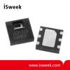
Miniature Digital Relative Humidity and Temperature Sensor
-
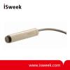
Probe Style Relative Humidity Sensor Module
-
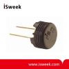
Capacitive Humidity Sensor
-
Voltage Output Temperature and Humidity Sensor
-
Humidity and Temperature Sensor Module
-
Voltage Output Humidity and Temperature Sensor Module
-

Voltage Output Temperature and Humidity Sensor
-
Temperature Humidity Sensor Module
-
Frequency Output Temperature and Humidity Sensor
-
Capacitive Temperature and Humidity Sensor


