Mouse over image to zoom

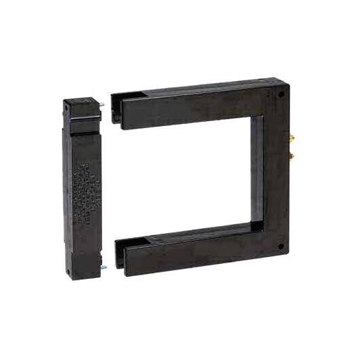
600 & 601 Series Split-core Current Transformer
-
Price
Price on request ≥1piece
-
Model Number
600 & 601 Series -
Data Sheet

-
Package
Original packaging -
Specs
600 & 601 Series -
Quantity
- +Send Inquiry
Find Similar Products
-

AC Current Transformer to DC Current (4-20 mA - Loop Powered)
Model Number:T201
MOQ:1
-

DC Current Trasducer to DC Current (4..20 mA - Loop Powered)
Model Number:T201DC
MOQ:1
-

Loop Powered Transmitter for Pt100 and Ni100 Probes
Model Number:T120
MOQ:1
-

Isolated Loop Powered Universal Temperature Transmitter
Model Number:T121
MOQ:1
-

Passive Current Transducers 100 ADC (4-20 mA - Current Loop)
Model Number:T201DC-100
MOQ:1
-

AC/DC Contactless TRMS Direct and Alternate Current Transformers
Model Number:T201DCH
MOQ:1
Product Description
The 600 & 601 Series Split Core Current Transformers are designed for assembly to an existing electrical installation without the need for dismantling the primary bus or cables.
600 & 601 Series Split-core Current Transformer Caution
Proper safety precautions must be followed during installation by a trained electrician. Never install while bus is energized. The current transformer must have its secondary terminals short circuited or the burden connected, before energizing the primary circuit.
600 & 601 Series Split-core Current Transformer Features
Construction: The core and windings are encased in UL approved plastic
Terminals: 8-32 brass studs with one flatwasher and two regular nuts
Flexible Leads: UL 1015 105° C, CSA approved, #16 AWG, 24” long unless otherwise specified
600 & 601 Series Split-core Current Transformer Specifications
Frequency: 50-400Hz
Insulation Level: 0.6 kV, BIL 10 kV full wave
Continuous Thermal Current Rating Factor: 1.33 at 30° C amb 1.00 at 55° C amb
Approximate Weight: 1.5 lbs.
600 & 601 Series Split-core Current Transformer Applications
For Energy Management Systems and Instrumentation
600 & 601 Series Split-core Current Transformer PART NUMBERS
|
Part Number |
Current Ratio |
VA at 1% Class |
ANSI Metering Class at 60Hz |
Part Number |
Current Ratio |
VA at 1% Class |
ANSI Metering Class at 60Hz |
|||||
|
BO.1 |
BO.2 |
BO.5 |
|
BO.1 |
BO.2 |
BO.5 |
||||||
|
600-401 |
400:5A |
1.5 |
2.4 |
|
------ |
|
601-401 |
400:5A |
1.0 |
4.8 |
------ | ------ |
|
600-501 |
500:5A |
2.0 |
2.4 |
|
------ |
|
601-501 |
500:5A |
1.5 |
4.8 |
4.8 |
------ |
|
600-601 |
600:5A |
2.5 | 2.4 |
2.4 |
------ |
|
601-601 |
600:5A |
2.0 |
2.4 |
4.8 |
------ |
|
600-801 |
800:5A |
5.0 | 1.2 | 1.2 |
2.4 |
|
601-801 |
800:5A |
2.5 |
1.2 |
2.4 |
4.8 |
|
600-102 |
1000:5A |
7.5 | 1.2 |
1.2 |
2.4 |
|
601-102 |
1000:5A |
5.0 |
1.2 |
1.2 |
4.8 |
|
600-122 |
1200:5A |
15.0 |
0.6 |
1.2 |
1.2 |
|
601-122 |
1200:5A |
10.0 |
1.2 |
1.2 |
2.4 |
|
600-152 |
1500:5A |
20.0 |
0.6 |
0.6 |
1.2 |
|
601-152 |
1500:5A |
15.0 |
1.2 |
1.2 |
1.2 |
|
600-162 |
1600:5A |
20.0 |
0.6 |
0.6 |
1.2 |
|
601-162 |
1600:5A |
15.0 | 1.2 |
1.2 |
1.2 |
|
600-202 |
2000:5A |
30.0 |
0.6 |
0.6 |
0.6 |
|
601-202 |
2000:5A |
20.0 | 0.6 |
0.6 |
1.2 |