Transimpedance Amplifier Board
-
Price
Price on request ≥1piece
-
Model Number
Digiboard -
Data Sheet
-
Package
Original packaging -
Specs
Digiboard -
Quantity
- +Send Inquiry
Find Similar Products
-

Broadband SiC Based UV Photodiode A = 0.06 mm2
Model Number:SG01S-18
MOQ:1
-

Broadband SiC Based UV Photodiode A = 0.06 mm2
Model Number:SG01S-18S
MOQ:1
-
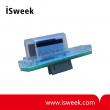
Reflective UV Sensor
Model Number:GenUV-L365P-MM
MOQ:1
-
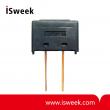
Reflective UV Sensor
Model Number:GUVF-P12MD
MOQ:1
-
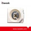
UV-A Sensor
Model Number:GUVA-S12SD
MOQ:1
-
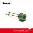
UV-A Sensor
Model Number:GUVA-T11GD
MOQ:1
Product Description
Digiboard Transimpedance Amplifier Board Description
Most applications of photodiodes and especially those in the ultraviolet wavelength range require special amplifiers because of the small photocurrents. Although the uv-sensors of sglux provide large active areas you mostly may consider using an amplifier.
To support your application development we provide you this completely new photodiode amplifier board. Based on our successful Multifunctional 2-Channel Amplifier Board we included additional features: one analog channel with adjustable Schmitt-Trigger (ST) and a Current-to-Frequency converter (CFC) channel.
The CFC clearly simplifies the integration of our photodiodes into digital- and microprocessor based designs.
Digiboard Transimpedance Amplifier Board Features
• wide single supply voltage range 5.0 V … 18.0 V with surge and polarity protection
• low power consumption ( < 50 mW @ 5 V )
• analog transimpedance amplifier channel with:
adjustable gain in the range 10 5 … 10 7 V/A with fine tuning option
Schmitt-Trigger stage with adjustable switching point and adjustable Hysteresis
LED for easy adjustment of the Schmitt-Trigger
• Current-to-Frequency converter with:
2 measurement ranges giving high dynamic range
standard CMOS compatible digital output
Important Notice
Please consider any possible action to protect the sensitive devices on the board against electrostatic discharge (ESD). Not to do so voids warranty.
Digiboard Transimpedance Amplifier Board Absolute Maximum Ratings
Exceeding these limits may decrease lifetime or destroy the board or parts of it immediately.
*in non condensing environment only
Digiboard Transimpedance Amplifier Board Electrical Characteristics
(at 25°C unless otherwise noted, default jumper settings)
General
Analog channel
* if fine tuning selected by closing switches 6 and 7 total gain derived by multiplying fixed gain with variable gain factor
Digital channel
* for the frequency output as well as for the Schmitt-Trigger output
Most applications of photodiodes and especially those in the ultraviolet wavelength range require special amplifiers because of the small photocurrents. Although the uv-sensors of sglux provide large active areas you mostly may consider using an amplifier.
To support your application development we provide you this completely new photodiode amplifier board. Based on our successful Multifunctional 2-Channel Amplifier Board we included additional features: one analog channel with adjustable Schmitt-Trigger (ST) and a Current-to-Frequency converter (CFC) channel.
The CFC clearly simplifies the integration of our photodiodes into digital- and microprocessor based designs.
Digiboard Transimpedance Amplifier Board Features
• wide single supply voltage range 5.0 V … 18.0 V with surge and polarity protection
• low power consumption ( < 50 mW @ 5 V )
• analog transimpedance amplifier channel with:
adjustable gain in the range 10 5 … 10 7 V/A with fine tuning option
Schmitt-Trigger stage with adjustable switching point and adjustable Hysteresis
LED for easy adjustment of the Schmitt-Trigger
• Current-to-Frequency converter with:
2 measurement ranges giving high dynamic range
standard CMOS compatible digital output
Important Notice
Please consider any possible action to protect the sensitive devices on the board against electrostatic discharge (ESD). Not to do so voids warranty.
Digiboard Transimpedance Amplifier Board Absolute Maximum Ratings
Exceeding these limits may decrease lifetime or destroy the board or parts of it immediately.
|
Parameter |
Unit |
Value |
| Operation Temperature range * |
°C |
0 … +70 |
|
Storage Temperature range * |
°C |
-25 … +85 |
|
Supply voltage |
V |
+18.5 |
|
Output current (digital output) |
mA |
0.5 |
|
Output current (analog output) |
mA |
10 |
Digiboard Transimpedance Amplifier Board Electrical Characteristics
(at 25°C unless otherwise noted, default jumper settings)
General
|
Parameter |
Unit |
Value |
||
|
min |
typ |
max |
||
|
Supply voltage |
V |
5 | 12 | 18 |
|
Power dissipation (at 5 V supply voltage, depends on load and switching frequency) |
mW |
|
50 |
|
Analog channel
|
Parameter |
Unit |
Value |
||
|
min |
typ |
max |
||
|
Fixed transimpedance gain (gain setting by switches 3,4,5) |
|
|
|
|
|
low |
V/A |
0.98 x 10⁵ |
105 |
1.02 x 10⁵ |
|
medium |
0.98 x 10⁶ |
106 |
1.02 x 10⁶ |
|
|
high |
0.90 x 10⁷ |
107 |
1.10 x 10⁷ | |
|
Variable transimpedance gain factor range* |
|
0.7 - 1.3 |
0.5 - 1.5 |
0.3 - 1.7 |
|
Input current |
A |
|
|
□ 30 x 10-6 |
|
Maximum output voltage (in both polarities) |
V |
□ 2.6 | □ 2.9 | □ 3.3 |
|
Output offset voltage (with optimal compensation) |
mV |
|
< □ 5 |
□ 10 |
Digital channel
|
Parameter |
Unit |
Value |
||
|
min |
typ |
max |
||
|
Output voltage LOW* |
V |
0 | 0.05 | 0.1 |
|
Output voltage HIGH* |
V |
2.8 | 3.1 | 3.3 |
|
Frequency output pulse length FWHM (levels above) |
µs |
1 | 1.2 | 2 |
|
Input current |
A |
~ 10-10 |
|
~ 10-4 |
|
Conversion rate |
|
|
|
|
|
low frequency mode |
Hz / A |
2.8 x 10⁸ |
3.0 x 10⁸ |
3.2 x 10⁸ |
|
high frequency mode |
3.1 109 |
3.3 x 10⁹ | 3.5 x 10⁹ | |
|
Conversion rate temperature dependance |
1 / K |
|
□3 x 10⁻⁵ |
|
|
Linearity error, high frequency mode |
|
|
|
|
|
@ 10 kHz |
% |
|
1 |
|
|
@ 40 kHz |
|
5.2 |
|
|
|
@ 100 kHz |
|
12 |
|
|
|
Linearity error, low frequency mode |
|
|
|
|
|
@ 10 kHz |
% |
|
1 |
|
|
@ 40 kHz |
|
5.5 |
|
|
| @ 100 kHz |
|
13 |
|
|


